User Settings
In the Settings dialog of Plant Modeller, the User Settings section allows you to specify settings that only affect your own use of the application.
Any changes you make to the user settings are only applied to your current Plant Modeller area; if you create a new area, it gets the default user settings from COS. However, there is a way to make your current user settings also available to new Plant Modeller areas you might create: when you change specific user-level settings and close the settings dialog, you are prompted whether to save your settings as defaults for your new areas. If you choose to do that and then create a new area, you are prompted whether to load the user settings for that area from the local file (personal defaults) or from COS (system defaults).

User Interface
In the User Interface settings, you can set options that affect the general user interface.
Input | Axis markers | HUD | User interface | Object identification labels | Ribbon tooltips | Highlight | Selection View | Assistance geometry | Restore point of interest and views | Reference grid
Input

-
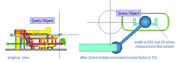
Zoom detail scale – Specifies the scale factor to use when using the Zoom Detail context-menu command or its shortcut, the apostrophe key ‘, to zoom the work view relative to the selected model object (regardless of the current zoom factor). Setting the factor to 1 means that model objects are shown in real size, for example the diameter of pipe DN100 is 114.3 if measured on the screen after zooming, and setting it to 10 means that the diameter of that pipe is 11.43 if measured after zooming.
-
Default step for cursor movement – Specifies how much the cursor moves each time an arrow button is pressed in Default cursor step mode. Value range 1-10000 mm, default is 100 mm.
-
Short step for cursor movement – Specifies how much the cursor moves each time an arrow button is pressed in Small cursor step mode. Value range 0.5-100 mm, default is 1 mm.
For a list of different movement modes, see Define cursor movement distance.
-
Zoomfactor with mousewheel events (3D) – Specifies the zoom factor to use when the user zooms in or out in a work view using the mouse wheel. Value range 1.005–10, default is 1.1.
-
Zoomfactor with mousewheel events (drawings) – Specifies the zoom factor to use when the user zooms in or out in a drawing using the mouse wheel. Value range 1.005–10, default is 1.1.
-
Zoomfactor with keyboard events – Specifies the zoom factor to use when the user zooms a view using the keyboard keys 1 (zoom in) and 3 (zoom out). Value range 1.005–10, default is 2.
-
Step for mousewheel rotation – Specifies how many degrees the viewing angle of a work view changes when the user scrolls the mouse wheel by one step while pressing Ctrl (for horizontal rotation) or Shift (for vertical rotation).
-
Step for mousewheel viewing angle – Specifies how many degrees the viewing angle of a bubble view is changed when the user scrolls the mouse wheel by one step.
-
Direct cursor mode – This setting is intended for situations where using the software via remote desktop or on virtual workstations is problematic and no better, platform-specific method exists for improving cursor behavior. Direct cursor mode allows you to use the arrow keys for moving even if the cursor position is locked. When moving a single object, the base point is set to the object's origin, and when moving multiple objects, the base point is the origin of the first selected object.
-
Classic navigation – Selecting this option enables the classic CADMATIC navigation mode. In this mode, the standard Windows cursor is disabled, and other parts of the application window are not accessible while the focus is in a work view. When this option is not selected, the cursor can freely access items in all parts of the application window, including ribbon menus, side panes, and objects in work views.
View cube & Axis markers

-
View cube size (mm on display) – Drag the slider to adjust the size of the view cube in work views. Value range 10–30.
-
Show axis marker – If selected, the axis marker is shown in work views.
-
Coordinate marker size (mm on display) – Specifies the size of the coordinate axis marker. Value range 10–50.
HUD

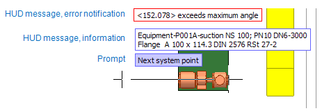
"HUD" stands for head-up display, and refers to displaying useful information where the user's focus point typically is (near the cursor).
-
Show messages in HUD – If selected, error notifications and other information are shown next to the cursor. If not selected, the information is only shown in the message pane (if displayed).
-
Show prompt in HUD – If selected, information about what the program expects the user to do next is shown next to the cursor and in the status bar. If not selected, the information is only shown in the status bar.
-
Show default messages – If selected, HUD messages are displayed using predefined values.
-
Customize messages – Opens the Choose tags to show in HUD dialog where you can select any supported tags to be displayed in HUD messages. The tags to show are defined separately for pipe, duct, and cable objects, and you can also create more contexts that will use their own tag settings.

User interface

-
Interface theme – Select the System default, Light, or Dark theme.
See also Visualization and Colors.
Object identification labels

The Object identification labels settings define which objects show identification labels in shaded views and what is displayed in these labels.
Select whether the following object types display a specific attribute value or values in the label, or no label at all.
-
Equipment
- Position ID
-
Valve, Instrument
- Position ID
- Position ID and NS
-
Pipe
- Pipeline
- Pipeline and NS
- Pipeline and Spool
- Pipeline, Spool and NS
-
Duct
- Ductline
-
Cable Tray
- Line Definition
-
Support
- Support Position ID
Note: If the selected option displays multiple values, the values are separated with the dash character: "Water-01 – 125". The "Position ID and NS" option can show the first three sizes from the Dimension Table, separated with the slash character: "V100-A - 80/100/125".
You can show or hide the labels as required by using the commands in the ribbon (see Identification labels) or in the 3D-digitize context menu, or with the shortcut keys Alt + Shift + L (show) and Alt + Shift + K (hide). Identification labels can also be shown in the Inspection View window, as described in Inspection View.
Ribbon tooltips

-
Show command ids for custom hotkeys in tooltips – Select this option to show the command ID (string or numeric) in the tooltip of buttons in the ribbon toolbar.
For more information, see Customizing the ribbon.
Highlight
-
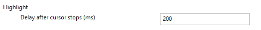
Delay after cursor stops (ms) – Species how many milliseconds the application should wait before highlighting the object under the stopped cursor. If performing a pick action and the object under the cursor is not highlighted, then the object cannot be picked in that context.
Selection View

-
Open the set browser view automatically when defining a set of objects – Select this option if you want set operations to automatically open a separate view that shows the selected objects.
The selection view can be manually opened and closed with the context-menu command Show selection (S).
Assistance geometry

These settings enable the visualization of assistance geometry points in work views. If these settings are disabled, you can still use navigation commands to navigate to a given assistance point, but there will be no visual cues indicating their locations in the model. Some point types are only visible in Plant Modeller, while others are only visible in Component Modeller. The color of a point indicates its type, as described in Plant Modeller Point Types and Component Modeller Point Types.
-
Enabled – Selecting this option displays pipe and beam center points and lets you choose which of the following additional point types to visualize.
-
Beam points
-
Center of gravity *
-
Centerline center points
-
Circle and arc center points
-
Connection points
-
Geometry points
-
Named points in component modeller *
-
Pipe branch points
-
Temporary geometry points *
-
Weld points
* Only visible in Component Modeller.
-
-
Maximum search distance (mm) – Specifies the maximum distance from the cursor to a displayed assistance point. Larger values allow users to see points that are further away from the cursor. Value range: 0–5000 mm.
-
Maximum view scale to visualize – Specifies the maximum view scale for displaying assistance points. Larger values allow users to zoom out more and still see assistance points. Value range: 1–200.
-
Delay after cursor stops (ms) – Specifies a delay for displaying nearby assistance points after the user stops moving the cursor. The smaller the value the more real-time the displaying of assistance points is between cursor movements, but smaller values might also cause irregular cursor movements in very complex models. Value range: 1–1000 ms.
-
Navigation command "Nearest geometry point (W)" should select pipe quadrant points in – Select where you want Move to nearest geometry point (W) to snap to quadrant points:
-
3D work views – Select this option to use the command in shaded and wireframe work views.
-
Drawing views – Select this option to use the command in 3D wireframe views displayed in drawings.
-
Restore point of interest and views to original position after

- Measure operation started from an input field
- Probe operation started from an input field
- Picking operation started from select component
When these options are selected, starting a Measure, Probe or Pick command from a context menu and completing the given action updates all work views so that they show the original point-of-interest and use the original filter box, if the user had navigated in the model or changed the filter box while performing the command.
For example, if you are inserting a Standard Component and use the Pick command to pick the component type from a previously inserted model object, after navigating to a suitable object and completing the picking action you usually want to get back to the location where the new component is to be inserted.
Clear the options if you do not want views and filter boxes to be automatically refreshed after using the specified commands.
Reference grid
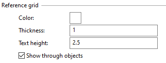
You can define the following settings for visualizing coordinate reference planes as grids:
-
Color – Click to select the grid color from a color palette.
-
Thickness – Define the grid line thickness (1–10).
-
Text height – Define the grid text height (1–100).
-
Show through objects – If selected (default), grid that is behind a model object is shown with a dashed line instead of a solid line. If not selected, grid is not shown when it is behind a model object.
For more information, see Coordinate references.
Tolerances

In the Tolerances settings, you can set the following options. Clicking Defaults restores the default values.
-
Minimum deviation from main axis – Specifies how many degrees a routed object should deviate from the nearest main axis before the program expects the deviation to be intentional. If the deviation is smaller than this threshold value, the program automatically corrects the route so that it aligns with the main axis.
Tip: To enable routes that deviate very little from the main axes, make sure the tolerance value is small enough (or zero).
-
Hit distance of objects – Specifies the maximum hit distance from the cursor to a target object (to its bounding box).
-
Hit distance of connection points – Specifies the maximum hit distance from the cursor to a target connection point (to the bounding box of the parent object; the object must be of permissible pick type).
-
Maximum distance to navigate to geometric entities – Specifies the maximum distance at which the cursor can navigate (snap) to a geometric entity.
3D Visualization
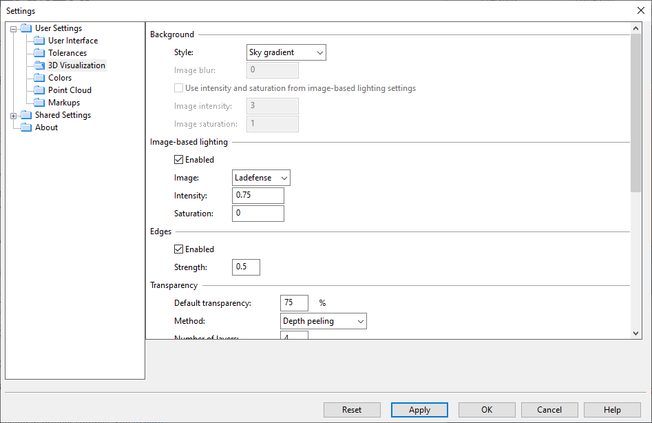
In the 3D Visualization settings, you can specify how objects are displayed in the 3D viewer in regard to lighting, transparency, and so on.
Different types of designs might require you to adjust the visualization settings to get the expected results. Most of the value fields support up to three digits, so that for example the edge strength of objects can be defined as 0.123.
The Restore Defaults button allows you to select one of these default configurations:
- Design Default – Default settings intended for design work.
- Design Performance Optimized – Default settings intended for design work using an older computer that does not have a modern GPU. Try this option if navigating in the model with 'Design Default' does not seem fast enough.
- Presentation Plant – Default settings intended for presenting plant designs to others.
- Presentation Ship – Default settings intended for presenting ship designs to others.
Background | Image-based lighting | Edges | Transparency | Point clouds | SSAO | Clipping | Anti-aliasing
Background

-
Style – Specifies whether 3D models are displayed against background color or background image.
- Default gradient – Displays a dark gradient background that transitions from black to dark blue.
- Sky gradient – Displays a sky-like gradient background that transitions from light blue to white.
- Solid – Displays a solid background using the first color of the color palette. See Colors.
- IBL image – Displays a background image, using the image specified in the ‘Image-based lighting’ settings. (Selecting this option enables image-based lighting and the other background options.)
-
Image blur – Specifies the amount of blurring to apply to the background image, from 0 to 1.
-
Use intensity and saturation from image-based lighting settings – If selected, the model and the background image use the intensity and saturation values defined in ‘Image-based lighting’.
-
Image intensity – Specifies the intensity of the background image, from 0 to 1000.
-
Image saturation – Specifies the saturation of the background image, from 0 to 1.
Image-based lighting

-
Enabled – If selected, a specialized image is used for applying lighting effects to shaded views, in addition to the normal lights defined in the views. You can select the image to use as well as its intensity and saturation.
-
Image – Select the image to use in image-based lighting. The image is also used as background image if specified so in the Background settings.
-
Intensity – Specifies the intensity of lighting, from 0 to 100.
-
Saturation – Specifies the saturation of lighting, from 0 to 1.
Edges

-
Enabled – If selected, objects in shaded views display dark edges.
-
Strength – Specifies the strength of edge lines, from 0 to 2 (thickest line).
Transparency
-
Default transparency – Specifies the transparency percentage of transparent objects.
-
Method – Specifies the method to use to display transparent surfaces that are on top of each other.
- Depth peeling – This method visualizes a transparent surface by considering the effect of each transparent surface behind it individually, up to the number of surfaces defined by Number of layers. This usually provides a fairly realistic visualization, but calculating the effect of many layers can affect performance.
- Weighted average – This method visualizes a transparent surface by forming an approximation of the colors of the overlapping transparent surfaces. This usually provides faster, but not necessarily realistic, visualization.
-
Number of layers – Specifies how many transparent surfaces can contribute to the color of a transparent surface, from 1 to 16. If the value is 1, a transparent surface is not affected by other transparent surfaces behind it; if the value is 4, a transparent surface is affected by the next three transparent surfaces behind it. Typically, larger values provide more realistic visualization while smaller values provide faster performance.
Point clouds

-
Style – Specifies the style in which points are drawn in point clouds.
- Billboards – Point is drawn as a quadrilateral that faces the viewer, using the user-defined billboard size.
- Points – Point is drawn as a simple point with a fixed size.
-
Billboard size – Specifies the size of the quadrilateral that is used when drawing point clouds in billboard style, from 0 to 1000 (largest size).
-
Color scale factor – Specifies the brightness of point cloud colors in work views and bubble views, using a scaling factor from 0 to 2. Values lower than 1 make point clouds darker, values higher than 1 make them brighter.
-
Use manual limit for VRAM usage – Active point clouds consume the memory of the graphics processor (GPU). Some of the points are stored directly in the GPU, and these points are drawn in every frame when the user is, for example, zooming or rotating a view. Normally the program detects automatically how much GPU memory it can use to visualize a point cloud. Selecting the manual limit option allows you to specify the maximum amount of memory the program can use per point cloud. Using a small VRAM budget allows point clouds to be visualized faster as fewer points are drawn on the screen.
Note: The point cloud cache folder and bubble view related settings are defined in User Settings > Point Cloud.
SSAO

-
Enabled – Screen Space Ambient Occlusion approximates the occlusion (diminishing) of light on objects in shaded views. When enabled, this technique can provide realistic, real-time shading effects without too much stress on the hardware.
-
Radius – Specifies the radius at which the ambient occlusion effect on each pixel is calculated, from 1 to 2000 (widest radius). Widening the radius should provide more realistic shadows, as long as enough samples are taken.
-
Samples – Specifies the number of samples to take from every pixel on the screen to approximate the occlusion effect, from 1 to 32. Increasing the number of samples should provide better quality, but it is also slower to apply.
-
Intensity – Specifies shadow intensity, from 0 to 4. Increasing the number makes shadows darker.
Clipping

-
Draw clip caps – If selected, the opening of objects that are clipped by the filter box or the front plane is drawn with a solid pattern. Otherwise, clipped objects are drawn as hollow.
Anti-aliasing

-
MSAA – Multi-Sampling Anti-Aliasing improves the visualization of very thin shaded (opaque) objects. This setting allows the visibility of each pixel to be calculated using 4, 8, or 16 subpixels. The higher the amount of subpixels, the thinner the visualized objects can be, but increased computation might slow down the visualization. Disabling this setting provides better performance, but shaded objects that are less than one pixel wide might not be visible. The setting has no effect on objects that are clipped by the filter box or the front plane.
Colors
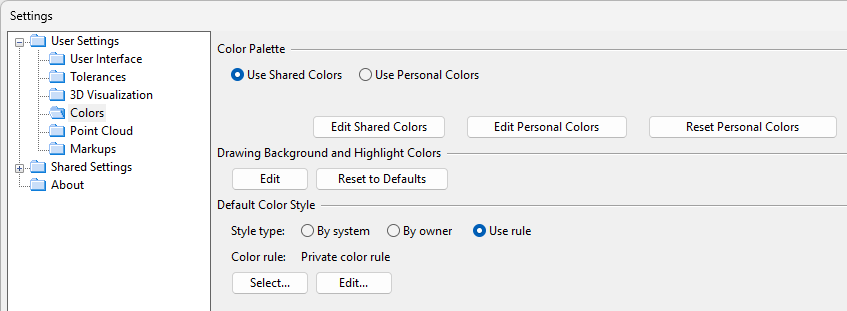
In the Colors settings, you can set the following options.
Color Palette
The color palette determines the colors that CADMATIC Plant/Outfitting uses both internally as well as in exported files. You can select which color palette to use:
-
Use Shared Colors (default) – Select this option to use the common color palette that your administrator can define for your organization in [library] > Configuration > Common > Colors or by clicking Edit Shared Colors in this view.
-
Use Personal Colors – Select this option to use the personal color palette that you can define by clicking Edit Personal Colors.
Reset Personal Colors resets your current personal color palette by replacing it with the common color palette that administrator has defined.
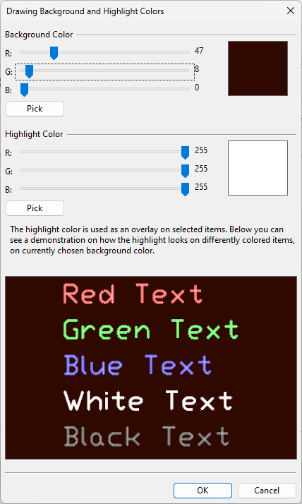
Drawing Background and Highlight Colors
You can change the background color of Document editor and the color that is used to highlight selected objects, without affecting document exports.
-
Edit – Opens the Drawing Background and Highlight Colors dialog.
-
Background Color – You can adjust the RGB values of the background color by dragging the color sliders or by clicking Pick and selecting the color from the color palette.
-
Highlight Color – You can adjust the RGB values of the highlight color by dragging the color sliders or by clicking Pick and selecting the color from the color palette.
-
-
Reset to Defaults – Restores the default background and highlight colors.
Default Color Style
You can set model objects in work views to be colored based on their system, their current owner, or surface shading rules.
-
By system – Select this to color the objects based on the System they use. For information on defining system colors, see Creating systems.
-
By owner – Select this to color the objects based on who owns them. For more information, see Color objects by ownership.
-
Use rule – Select this to color the objects based on a Surface shading style.
-
Select – Opens a list of available surface shading styles for selecting which style to use.
-
Edit – Opens the current style for editing.
-
The default color style is used in work views unless you change the color style from the properties of an individual view (Color Style) or from Home > Visualization control > Change color style.
Point Cloud
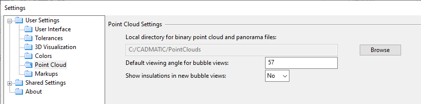
In the Point Cloud settings, you can set options that affect displaying of point clouds.
-
Local directory for binary point cloud and panorama files – Specifies the local directory where the imported point clouds and their panorama files (in Panoramas subfolder) are stored in native CADMATIC binary format. Click Browse to select the local folder to use (it cannot be a shared network drive).
-
Default viewing angle for bubble views – Specifies the viewing angle to use with the Zoom Extents context-menu command (its shortcut key is the semicolon character ";"). This also specifies the default viewing angle (degrees) for bubble views. Value range: 1 (most zoomed-in) – 160 (extremely wide angle).
-
Show insulations in new bubble views – Specifies if new bubble views should show insulation by default.
Note: The point type and other visualization-related settings are defined in User Settings > 3D Visualization > Point clouds.
Markups
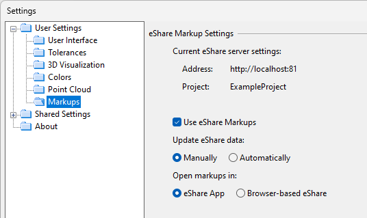
In the Markups settings, you can set options for loading markups from CADMATIC eShare.
-
Current eShare server settings displays the eShare server address and the name of the project in eShare, as defined in Settings and Actions.
-
Use eShare Markups – Select this option to enable Plant Modeller to load markups from eShare and list them under eShare Markups in the model tree.
-
Update eShare data – Select how to load markup data from eShare:
-
Manually – Markups are loaded from eShare when you select eShare Markups in the Model Tree pane and then click Update in the Properties pane.
-
Automatically – Markups are loaded from eShare when you click
 to open the eShare Markups list in the Model Tree pane.
-
-
Open markups in – Select how to open eShare when you click Start eShare in the property pane:
-
eShare App – Select this option to use eShare App for viewing markups. If the application is not found, a web browser opens instead.
-
Browser-based eShare – Select this option to use the default web browser for viewing markups in eShare.
-
For more information on markups in the model tree, see Managing markups in the tree.
For general information on eShare integration, see Working with CADMATIC eShare.